Case study · Component design under real constraints
A Desiccant Wheel for Window AC Units
Team engineering-design project: an activated-alumina desiccant wheel that dehumidifies window AC units using the unit's own waste heat. I built the physical test rig and owned the CFD study that set the duct-to-wheel gap tolerance.
The problem
Humidity makes heat more dangerous — it stops sweat from evaporating, which is the body’s main cooling mechanism, and it drives up the load on conventional air conditioning. Desiccant wheels — rotating discs of moisture-absorbing material that get dried out (“regenerated”) with heat and reused continuously — are being trialed as a way to pre-treat humid air before it’s processed in large buildings, but it’s not standard practice there yet, let alone at window-AC scale.
Working in a five-person team through Columbia’s engineering design sequence (MECE E3420/E3430), we set out to scale a desiccant wheel down to something that fits inside a residential window unit — and to regenerate it using heat the unit was already producing as waste, instead of adding an external heater. That second constraint is the whole point: a window AC’s condenser only gives you about 110–120°F to work with, well below the ~300°F regeneration temperature typically stated for activated alumina. The design had to work at a temperature it wasn’t supposed to work at.
Design and fabrication
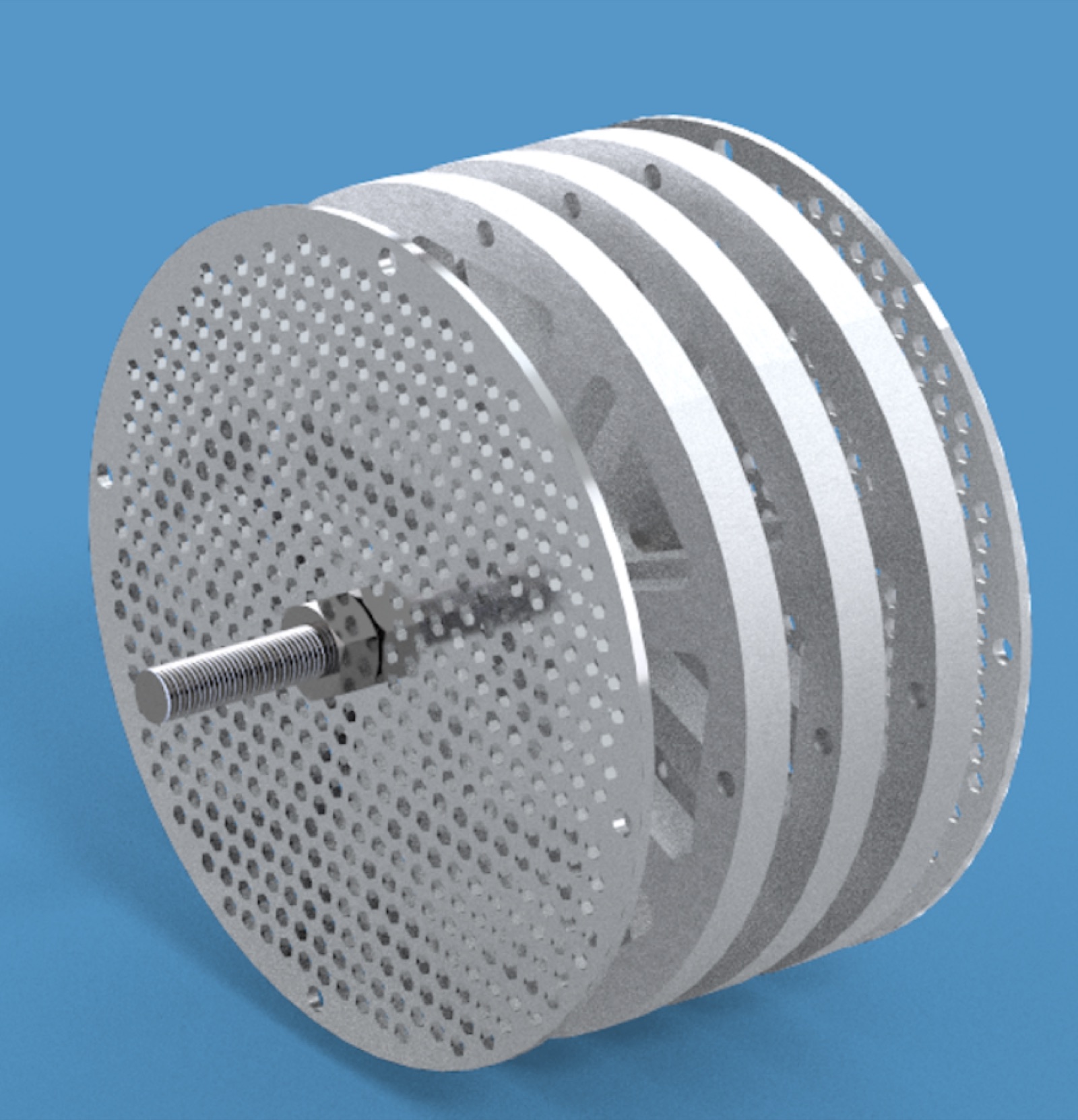
We chose activated alumina as the desiccant — easy to handle, regenerates well, minimally toxic, and well characterized in the literature. Early validation used a 3D-printed wheel just to confirm the material would absorb and release water the way we expected. From there we machined a second prototype from steel and aluminum and screened several internal configurations (aluminum-only, steel-only, mixed). Aluminum picked up moisture fastest, but the steel configuration dried more evenly, so we built the final test wheel around three internal steel plates (4.75 mm each) sandwiched between two perforated aluminum face plates. Test wheel diameter was 4 inches; the planned integrated size for an actual window unit was 10 inches, set by the internal envelope of a standard unit.
Testing
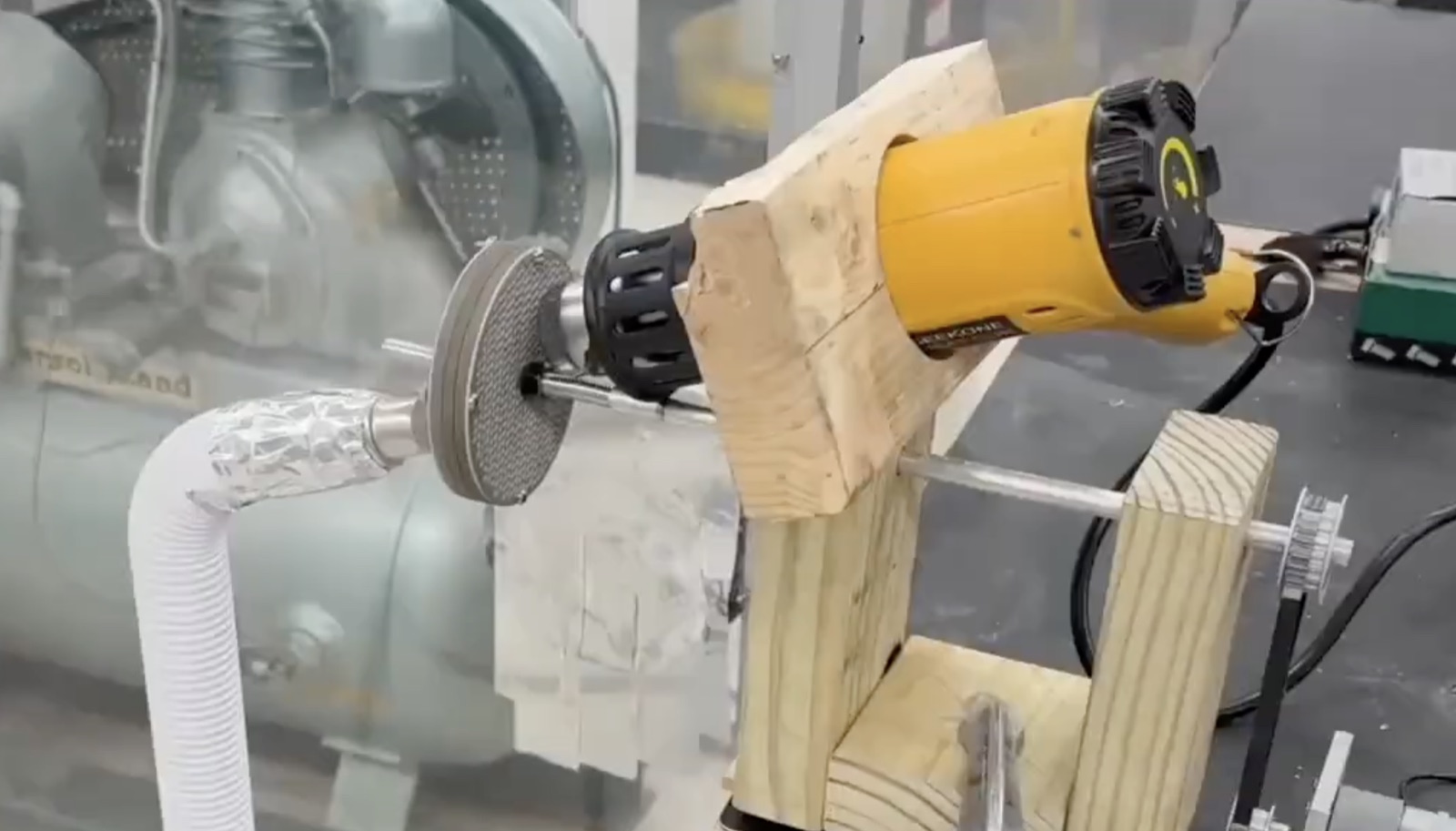
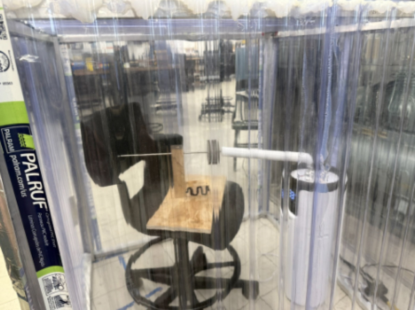
I built the test rig: a 4×4×4 ft humidity chamber out of corrugated plastic panels on an aluminum frame, driven to roughly 90% relative humidity with a commercial ultrasonic humidifier. We weighed the wheel on a scale accurate to ±0.01 g before and after each stage to track moisture uptake and removal directly, then dried it with a stationary heat gun held at the 110–120°F range we were targeting. We ran three repeated trials, plus a final proof-of-concept test with the wheel actually rotating — humidified air on one side, heat on the other, running simultaneously.
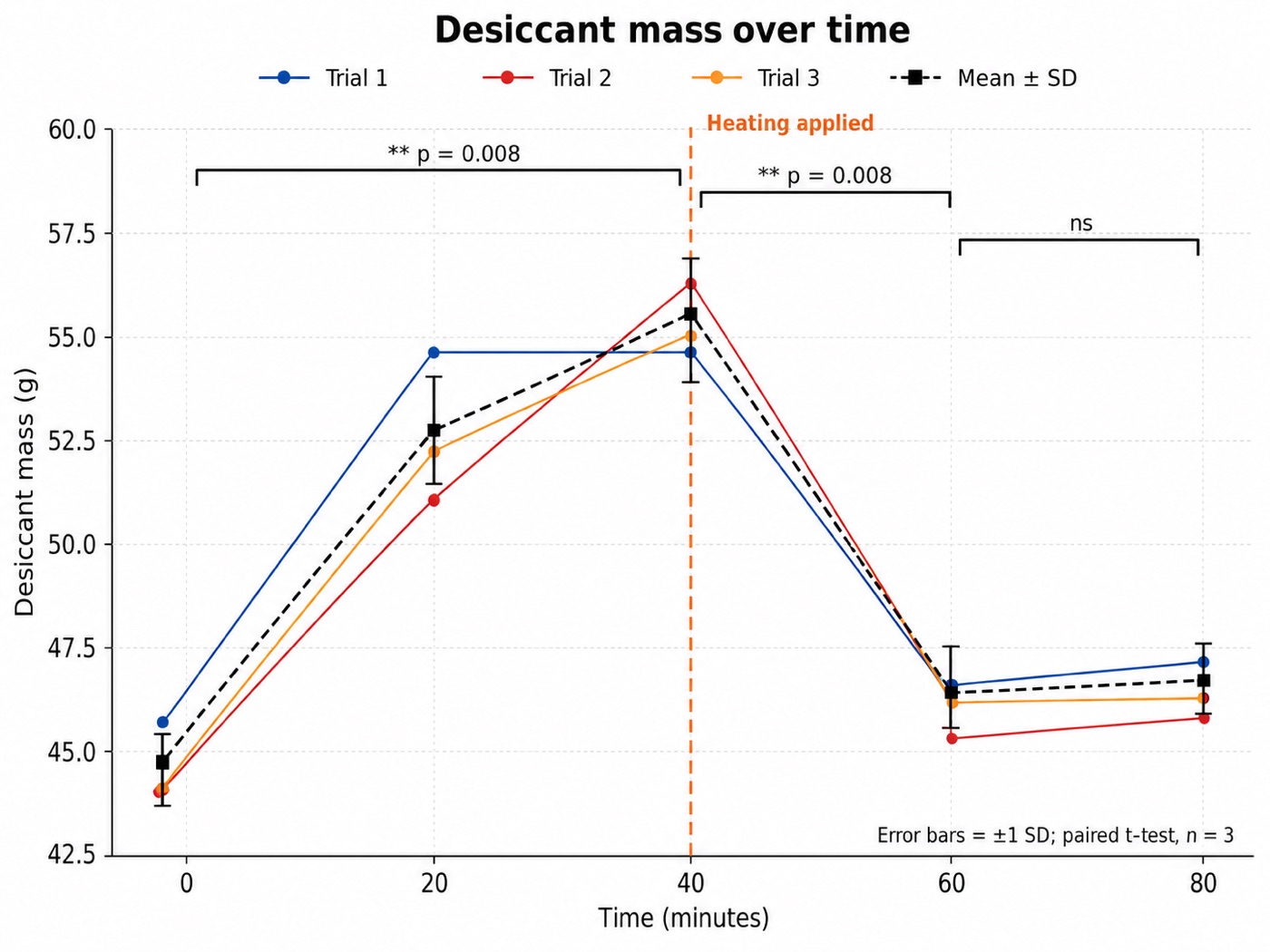
Results: average moisture uptake of 25.5% of dry desiccant mass over a 40-minute exposure, and average regeneration efficiency of 83.3% after 20 minutes of heating — at a temperature far below what commercial systems use. Paired t-tests confirmed both the uptake and the regeneration were statistically real (p = 0.008 for each), and that most of the regeneration happened in the first 20 minutes rather than needing the full 40. Scaled to the planned 10-inch wheel, that performance corresponds to roughly 72–94 W of latent cooling load taken off the compressor — about 22–29% of the total dehumidification capacity of a representative 5,000 BTU/h window unit.
My piece: sizing the gap
Once the desiccant itself was validated, the open question was mechanical: the wheel has to rotate inside stationary ducting, which means there’s a gap, and air leaking through that gap never gets dehumidified. A rotary seal would solve it cleanly but adds cost and complexity we didn’t want. I took on the CFD study to find how tight that gap actually needed to be.
CFD methodology and iteration ANSYS Fluent, mesh iteration, gap-leakage study
I had access to a student license for ANSYS Fluent, which caps a model at 1.3 million mesh elements — small enough that getting a usable geometry took three real attempts.
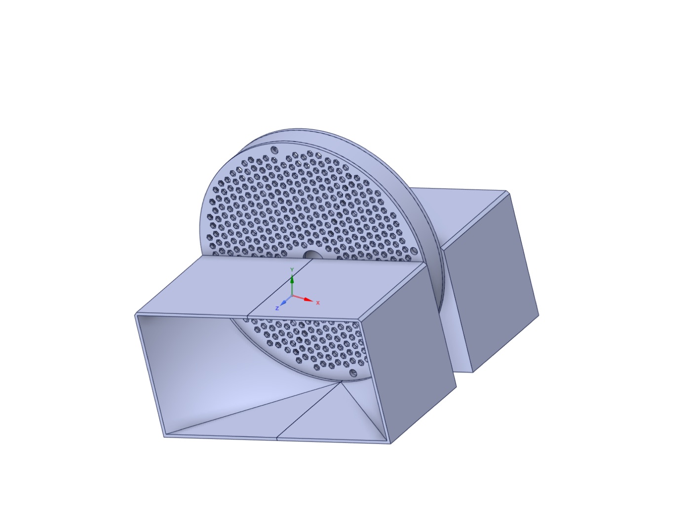
Design 1 modeled the ducts as thin solid bodies rather than a clean enclosed fluid volume. Combined with the full wheel geometry, that pushed the surface mesh count past what the license would allow before the model ever reached a working volume mesh.
Design 2 simplified the geometry by cutting the model at a symmetry plane and removing half the wheel, which got past the meshing wall — but introduced a new problem: a curved duct wall that approached a flat wall asymptotically. The nearly-tangent surfaces caused the mesh to overlap and Fluent couldn’t build a continuous surface across them. I reshaped the inlet duct into a quarter-circle so no curved edge merged gradually into a flat one.
Design 3 finally meshed cleanly, but the outlets sat too close to the wheel, producing backflow that made the results hard to interpret. Adding extension walls at the gap outlet gave the flow room to develop before it hit the pressure-outlet boundary, which became the final working geometry.
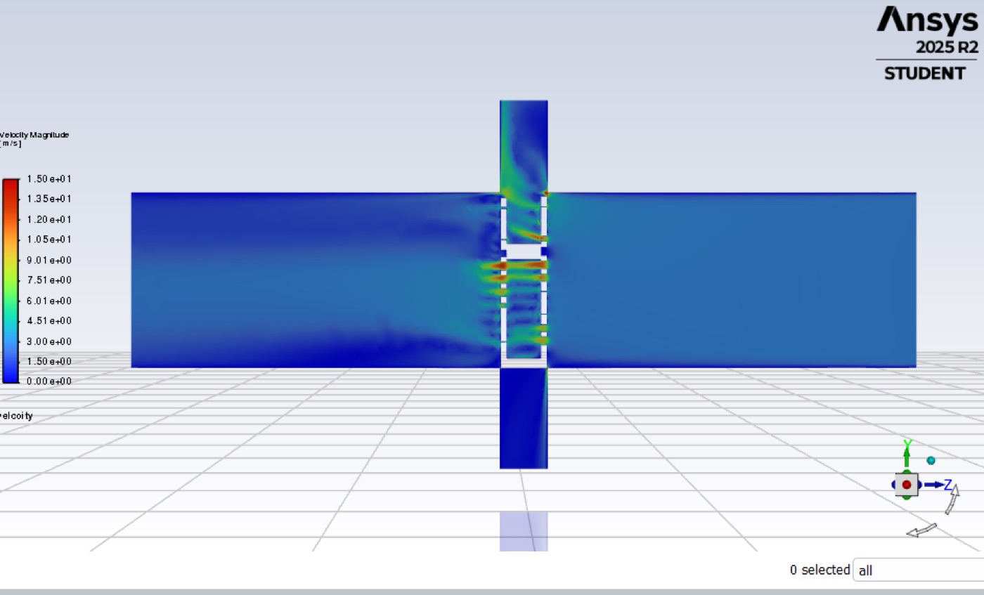
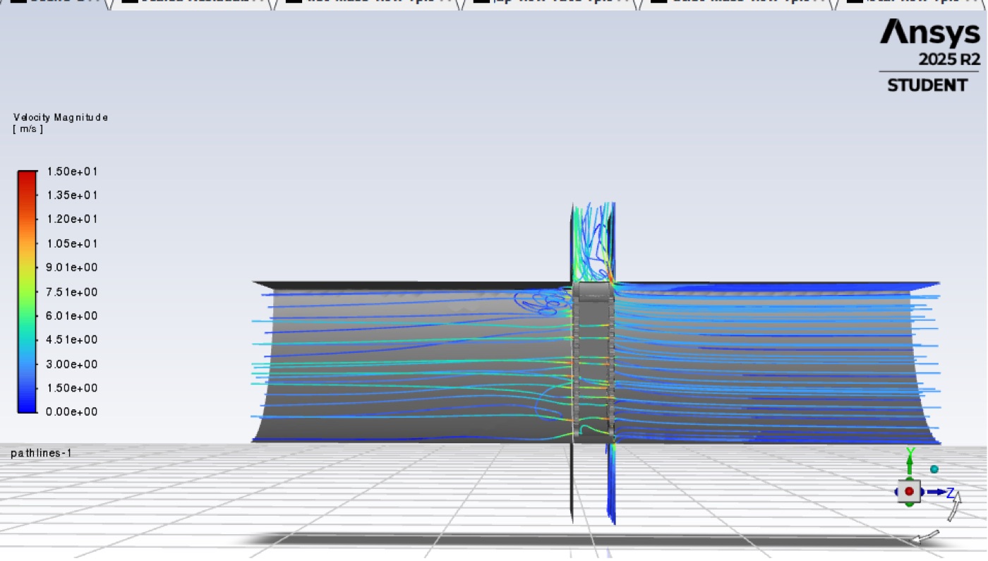
With that geometry, I ran a RANS solver with a k-omega turbulence model at three gap clearances — 0.10 in, 0.05 in, and 0.01 in — at an inlet velocity matching a 160 CFM target flow rate. Reducing the gap from 0.10 in to 0.01 in increased the share of inlet flow reaching the main outlet from 50.7% to 73.9%, with mass-conservation error under 0.006% across all three cases. That pointed to roughly 0.01 in as the design target, with the caveat that the mesh resolution in that same gap region was the part most constrained by the element cap — exactly where the answer mattered most.
What I’d do differently
The simultaneous rotating test separated the humid and hot zones only by physical position and the fact that warm air rises, not by real ducting — some mixing between the two was inevitable, which means the measured net moisture gain is a conservative floor on what a properly ducted wheel could do. The CFD model also only simulated airflow, not moisture transport or heat transfer, so it answers “how much air bypasses the wheel” but not “how much that bypass costs you in dehumidification.” A full system model that couples both would be the natural next step.
All selected work