Case study · Mechanism design, fabrication & controls
A Four-Bar Linkage on a $100 Budget
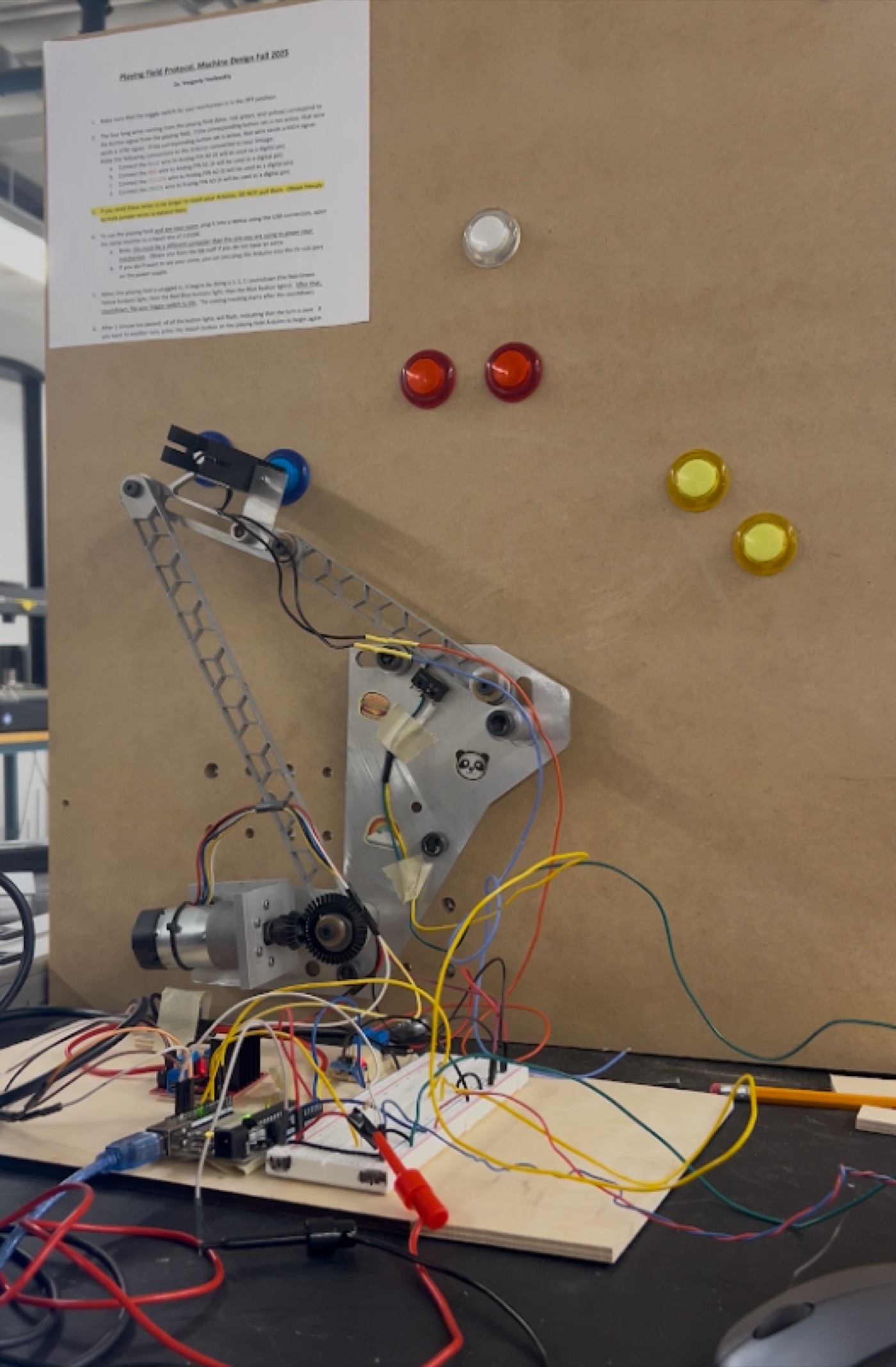
Team of four in Machine Design. Designed, machined, and wired a four-bar linkage that reaches out and presses buttons on a game board on command — under a $100 parts budget, scored on buttons pressed and minimum linkage volume.
The problem
Machine Design (MECE3409) assigns every team the same core challenge: build a mechanism, driven by a single motor, that has to physically press specific buttons on a wall-mounted game board in response to a signal, then get scored on a live timed run. Two things made it a real design problem instead of a build-anything exercise: a parts budget under $100, and a scoring formula based on how many buttons the mechanism pressed during a trial plus the linkage’s minimum volume across its functioning positions, checked once at the end of the run rather than tracked continuously — the smaller that minimum footprint, the better the score.
Design
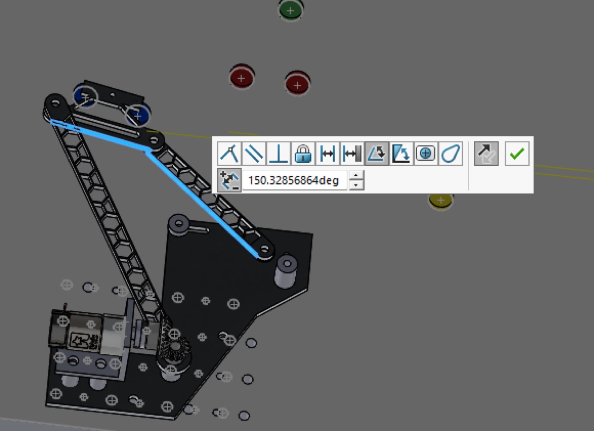
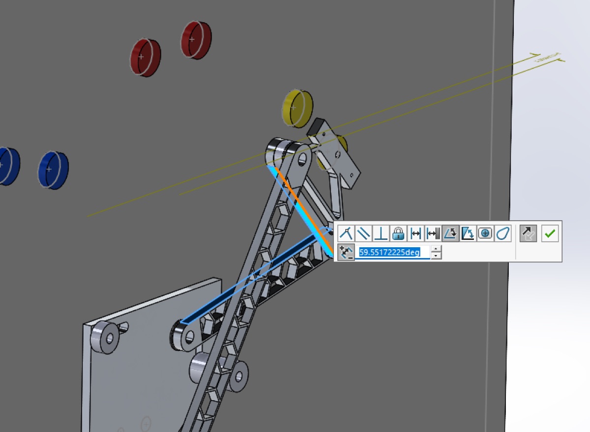
Our four-person team modeled the mechanism as a four-bar linkage in SolidWorks and analyzed the transmission angle — how efficiently the linkage transmits force — at both extremes of its travel, since a linkage that binds up or loses mechanical advantage at the edge of its range isn’t reliable under time pressure. The final geometry held a transmission-angle deviation of about 30° on one side and 60° on the other from the ideal 90°.
What I built
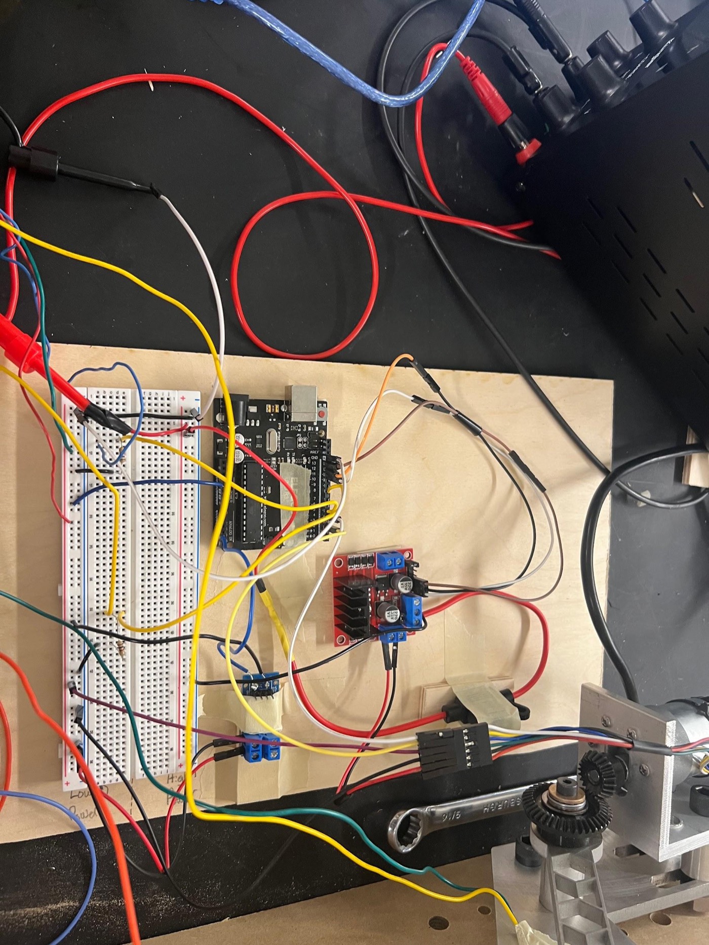
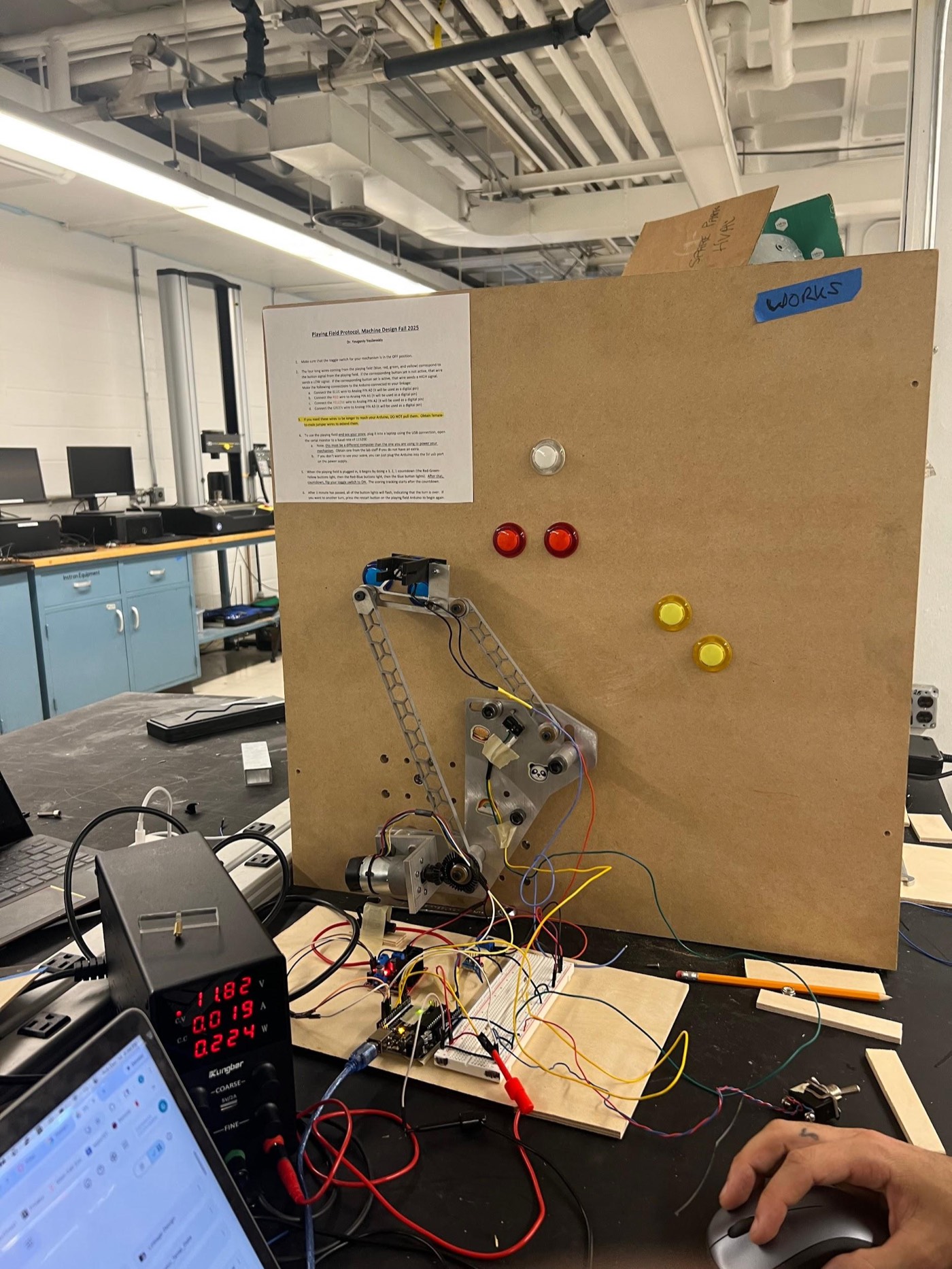
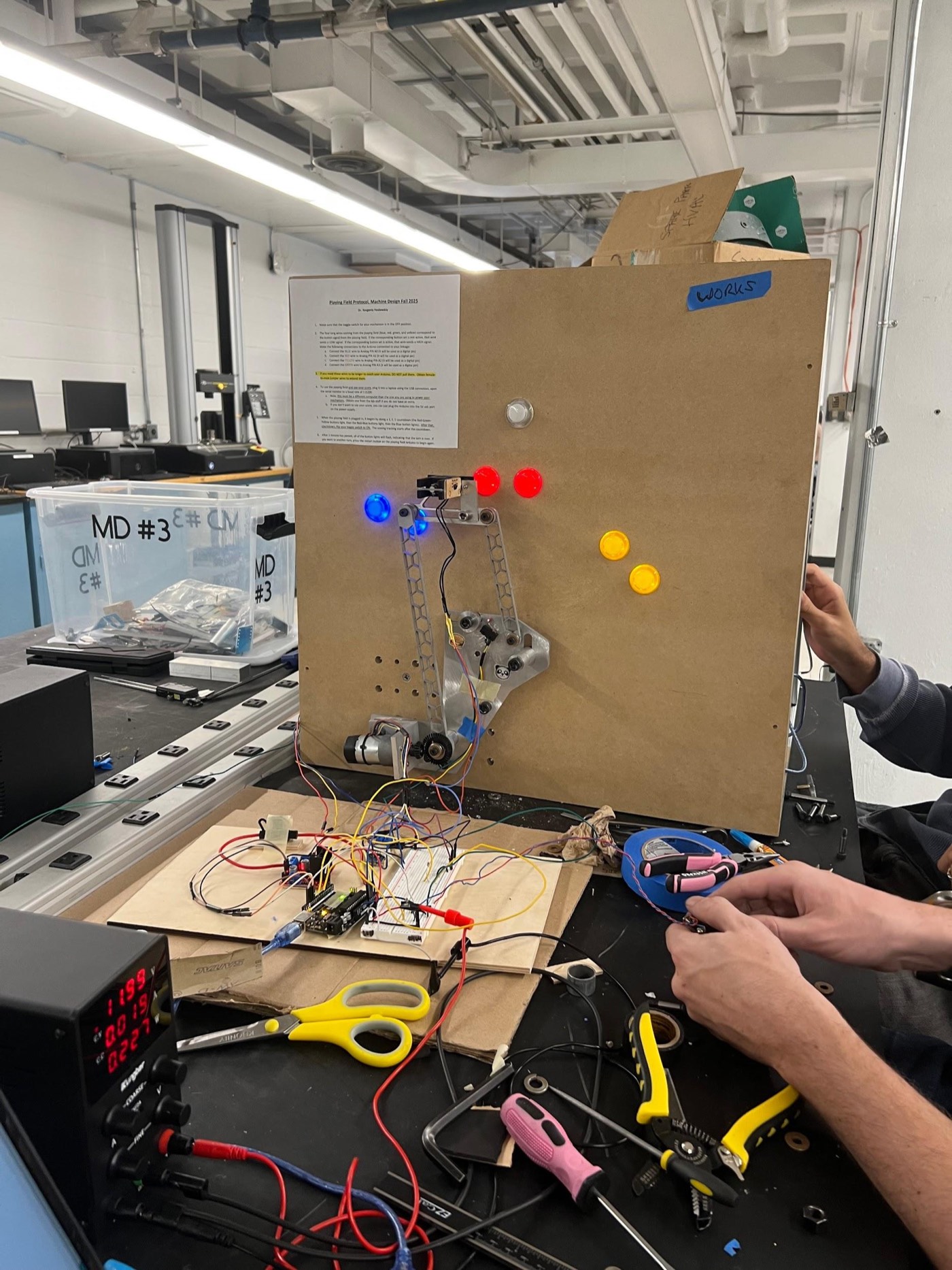
My part of the build was fabrication and the PID control programming. I machined the structural components with a water jet and CNC mill, built the custom jigs that made the parts repeatable across iterations, and programmed the control system: an Arduino driving the motor through a PID controller, homed against a limit switch, with a toggle switch for manual control during testing and calibration.
Electronics and controls motor driver, limit switch, PID tuning under real friction
The control stack was straightforward on paper and finicky in practice: an Arduino running a PID loop against a motor driver board, a limit switch for homing so the linkage always started from a known position, and a manual toggle switch for direct control during bring-up and testing. Total parts cost — bevel gears, a push-pull solenoid, 3D-print filament, and hardware — came to $91.45, under the $100 requirement with some margin.
The PID tuning itself was the hardest part, and not for a software reason. Every time the linkage ran, the joint bolts — hand-tightened with a 1/8 in Allen key, since we didn’t have a torque wrench to set a consistent spec — loosened slightly, which changed the friction in the joint and threw off an already finicky tune. Loctite was on the table, but we ruled it out: it would have fixed the tightness in place, which meant we’d lose the ability to keep adjusting it as we iterated. With a real time crunch bearing down and too many variables to isolate cleanly, the honest fix on test day wasn’t a clean root-cause solution — it was tighten, run, watch the score, and adjust.
Testing
On the final graded run, the linkage reliably reached all three button positions in sequence and scored 72 on the class’s test protocol.
What I’d do differently
The real fix isn’t a smarter PID gain set — it’s a torque wrench and a real spec. Without one, tightness was a guess, which meant friction was a guess, which meant every tuning session was partly re-solving a problem I’d already solved the run before. A defined torque spec (and probably a thread-locking approach that still allows planned re-tightening, rather than a permanent one) would turn “guess and see if the score improves” into an actual repeatable process.
All selected work